Nip Control Tools
NIP Inspector
The NIP Inspector tool supports the Nip Control Systems Measurement products including the Nip Width Indicator and the Nip Pressure Indicator. These products provide a digital measurement for Ink Roller stripe and Cylinder Pressures, two variables that greatly affect dot gain (TVI) variations.
Nip Width Indicator (NWI) is designed to digitally measure the Ink Roller Stripe for each unit and allows the operator to immediately adjust the roller while the NWI is in the ink roller nip to get the stripe to the correct value. This “digital measurement of the stripe” should be done at least once a week to ensure the ink rollers are set correctly. The ChromaChecker accountability inspector provides the ability to associate a responsible operator(s) for every device (including the Nips for the press) and define when periodic measurements have to be taken to ensure the Nips are consistent. Accountability inspector will send email notifications to ensure this process is completed on a timely basis, and alerts if the device fails or goes beyond the defined time period ensuring the Nip Ink Roller stripes are maintained in a consistent manner.

Nip Pressure Indicator measures the plate to blanket pressure and the impression cylinder to blanket pressure in each unit of the press. Ideally, the cylinder pressures should be as low as possible to still produce good ink transfer, and the units should be consistent to one another in order to allow for different inks to be moved between units. Today, most units are found to be greatly over pressed (too much excess pressure), and inconsistent to one another. Using the Pressure Indicator, the operator can baseline the units to a common, low-pressure value which not only saves electricity, but saves tremendous wear and tear on the press, and provides for consistent imaging with all inks in all units. The Nip inspector will track the cylinder pressures over time and the ChromaChecker Accountability Inspector defines reminders to the responsible operators to ensure press is maintained properly.
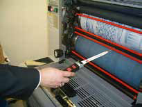
How the Nip Width Indicator measures Ink Stripe: Record values in ChromaChecker Nip Inspector
The NIP width indicator tool allows press operators to digitally measure the ink roller stripes for each unit of a press and instead of “eye-balling what 4mm stripe is, the operator can digitally set the ink rollers on the fly to a “measured” 4 mm strip. The values can then be entered into ChromaChecker color cloud via the Ipad App interface to document that the Nip widths has been checked within the defined time frame as shown here:
and the Nip icon in the Print dashboard will turn green showing it has been checked and they are good
The time frame for checking the Nip is defined within the ChromaChecker Nip inspector. The Accountability Inspector enables the email notifications which are sent to the responsible party the day before the defined deadline, and if not acted upon, the day after expiry. If the Nip is not checked within the defined time frame, the icon in the dashboard will turn yellow communicating that the Nip condition is unknown. If the Nip fails the defined values the icon turns red highlighting that there is an issue with the Nip ink stripe values.
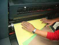
Auditing Plate to Blanket and Blanket to Impression pressures to determine course of action.
The Nip Pressure Indicator is used to measure the Plate to Blanket pressure within each unit and the pressure values can be entered into ChromaChecker via the iPad app to document the condition of the pressures in each unit. The pressures are critically important since they directly affect dot gain (TVI) within each unit of the press. The pressure for all units should be documented before any Plate Curves are built or ICC Profi le targets printed. Ideally, the NIP pressure values have to be documented to establish a “repeatable baseline” to come back to in the future. The plate curves will only work for the pressure conditions of the cylinders when the plate curve targets are imaged on the press. The cylinder pressures should be set with minimum pressure and consistent to one another before a baseline is established. Measure all the cylinders and enter all values in ChromaChecker Nip Inspector.
(Can Measure 2-9 measurements per cylinder- keep track of location on cylinder if measuring around cylinder)
Once all data has been measured and entered, compare the unit pressures to one another by selecting INTER Unit variation, upper left corner. Ideally, the cylinder pressures should be uniform to each other, They are often different, and when they are, you will want to focus on the lowest pressured unit, as long as you are experiencing good image transfer from the unit, you will want all the other units normalized to this pressure value.
When comparing values in “Inter-Unit” mode, look for the lowest values, in this example, all units average around 600N/cm2 which is fairly high compared to most presses that we have worked with. Most presses can provide good image transfer at 400 N/cm2 or less (33% less press which means substantially less energy and wear and tear on press). If granted time to dig into the press, take one unit down to 400 N/Cm2 and see if you still can get good image transfer. If so, then take all units to this new lower value and test image transfer. If this is successful, understand that your dot gain (TVI) will probably be lower than before, so your prints may look sharper.
This is a great time to update your plate curves with the single strip G7 ChromaChecker™ target.
Units are traditionally over pressed which causes undo wear and tear and much higher energy consumption.
This resetting of units on the press will take some time, but this will provide an efficient baseline for future process control on the press, with smaller, more natural TVI. Ideally, you will want all the units within 20% of one another which will minimize variations should you need to run the same ink on different units for different jobs, or if you want to move the CMYK inks between units for some jobs.
Next, change the unit setting (upper left corner) to “Intra-Unit” values. This compares the pressures taken within the same unit. If you see pressure values within the same unit vary by more than 20% please conduct a “break away” solids test. This requires plating a solid square covering the entire image area for the cylinder in question. Start with normal impression and transfer ink to paper, then back off the pressure slowly, outputting paper versions showing the condition of the cylinder and blankets at reduced pressure settings.
Intra-Unit Comparison: Course of Action
(Look at the brown values on the Cyan Cylinder, a break away test should be done to check the condition of this cylinder)
(Notice the pronounced unevenness across the cylinder: darker in upper left, lighter in lower right, and two distinct circles)
This simple test will provide a good indication of what condition the cylinders and blankets are in, and help you in determining when they should be changed out due to quality issues that otherwise would be very difficult to diagnose.
Using the ChromaChecker Nip Inspector tool with the Nip Control Systems devices allows for process control on a mechanical level that was never possible before. You can now create baselines for Cylinder pressures and monitor over time, and digitally measure ink roller stripe and ensure that each operator is seeing 6mm identically.
This is a sample of a break away solid on this Cyan cylinder: notice the inconsistencies of ink distribution.
Defining “Normal” Baseline for Nip Cylinder Pressures
Once you have your cylinder pressures measured and defined you will assign them as your baseline and you will be ready to build your plate curve, or ICC Profifi le for this condition.
(Here is a list of measurement data for the Nips, select the measurements and click on blue button: Create Baseline)
You will want to create a baseline for the cylinder pressures every time you before you build a plate curve or ICC Profi le for your device. This will allow the press operators to react should the TVI change in the future, they will be able to compare their current pressures to the baseline pressures which were established when the curve was built in order to understand how to get back to a “normal condition” over time, which will prolong the useful life for the plate curve and or the ICC Profile that represents of the output device color condition.
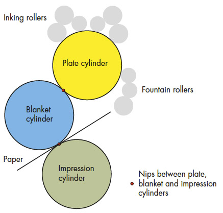
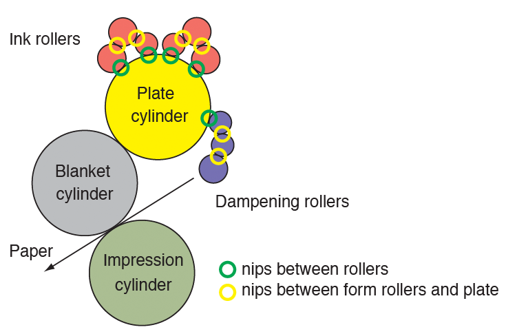
Where to measure in the printing press:
Nip Width Indicator (NWI)
Nip Width Control’s Sensors
The sensors are developed primarily for roller nips (yellow) and nips between the plate and the form rollers (green),
where the nip pressure is lower than between cylinders.
The sensors are good for more than 500 measurements.
| Nip Width: | 2 - 20 mm | 5-50 mm |
| Roller Diameter: | 30 - 200 mm | |
| Nip Temperature: | 20 - 50° C | 20 - 50° C |
| Roller Surfaces: | Metal / Rubber Hard Plastic / Rubber Rubber / Rubber |
Metal / Rubber Hard Plastic / Rubber Rubber / Rubber |
| Rubber Hardness: | 20 - 60° shore A | 20 - 60° shore A |
Water Resistance & Cleaning
- Nip Width Indicator: IP 20. Sensor: IP 65
- Always wipe the sensor clean after measuring
- Do not use solvents
Easy to Use
- One-button control
- Only one operator needed
- Bright LED display for easy readings
- Indicator lights when correct or incorrect measurement
- Automatic shut-off for maximum use of standard batteries (AAA): Lifespan exceeds 1000 measurements
- Sensors can measure with either side towards either roller
- 3-step safety front guards the operator
- Developed for both roll and sheet offset printing presses, and small and large presses from various manufacturers
Nip Pressure Indicator
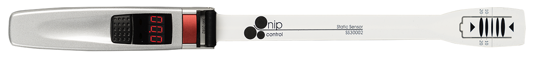
The PRESSURE INDICATOR™ measuring system consists of a hand device, a flexible sensor blade and a calibration tool
Pressure Indicator instrument
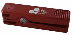
Calibration tool
Print quality depends on best possible transfer of the ink and water emulsion - from the plate cylinder, to the blanket and finally the paper.
Thanks to the new, innovative PRESSURE INDICATOR™, it is for the first time possible to quickly measure the nip pressure between cylinders, rather than the height of the blanket, which is an indirect measurement.
With Nip Control’s PRESSURE INDICATOR, it is easy to monitor how the nip pressure changes over time, or how the pressure changes with different underpackings and blanket compressibility.
Easy to Use
Let the cylinders pull the extra thin sensor blade through the nip, and in the display you will instantly see the nip pressure.
Peak Value
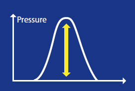
All nips have a pressure curve. The PRESSURE INDICATOR monitors how the pressure increases when the sensor blade is moving through the
cylinder nip (Rolling Nip™). The instrument then shows the peak pressure value on the display.
Where to measure in the Printing Press:

User friendly:
- One button control
- Only one operator needed
- Bright LED display for easy readings
- Indication if start-up without calibration
- Standard AAA batteries and power save function
- Sensor can measure with either side towards either cylinder
- 3-step safety front guards the operator
- Can be used on all offset presses from all manufacturers
Specification:
- Sensor length 350 mm
- Sensor thickness 0,2 mm
- Nip width > 5 mm
- Cylinder diameter All sizes
- Nip temperature 10 - 70° C
- Cylinder surfaces Metal to Rubber and Rubber to Rubber
- Rubber hardness < 95° shore A
- Measurements per sensor >2.000
- Measuring unit (force/area) Newton/cm² (N/cm²) & Nip Pressure Value (NPV)
- Measurement range 200 - 650 N/cm² & NPV
- Display resolution 10 N/cm² & NPV
- Patent SE-519 918 and Patent Pending
|
Pressure Indicator instrument |
Part Number |
P101 |
|
|
Sensor blade |
Length 350 mm | Part Number |
PS35001 |
|
Calibration tool |
Part Number | DS30001 |
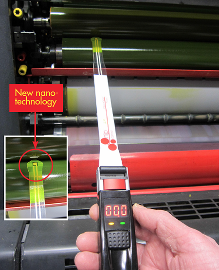
PRESSURE INDICATOR™ – Low Pressure version - NEW!
unique measuring system for offset roller nips
A true revolution
New nanotechnology enables control and setting of the pressure between offset rollers, ensuring a stable printing process and a reduction in the cost of consumables. At present, most printers still set rollers by estimating an ink stripe – the visual imprint when two rollers are pressed together. The conventional ink-stripe setting method completely fails to measure nip pressure, which is the crucial process factor.
Shear force & peak pressure
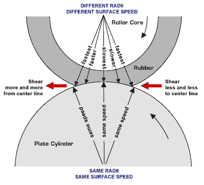
The ink and dampening solutions are processed and transported by the “shear force” created when two roller surfaces are in contact under pressure, with different surface speeds.
Besides the shear force, the offset process is also affected by ink adhesion to the rollers (viscosity) and surface roughness.
Rubber change = nip change
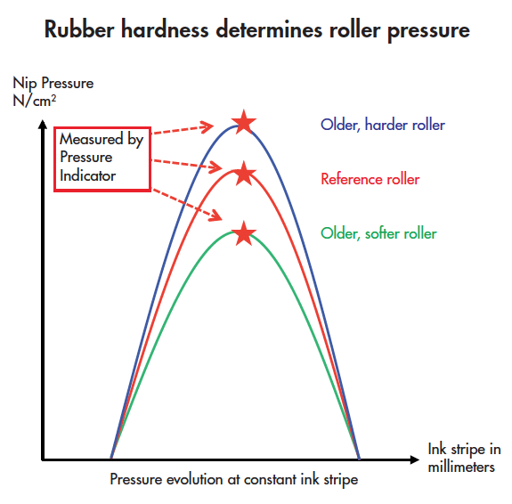
When adjusting a roller nip, a common error is applying excess force to maintain a consistent ink stripe in spite of aging rollers, as they lose their flexibility and become harder.
Consequently, to maintain a consistent ink stripe, the rollers are forced together with increasing force over time – resulting in incorrect and excessive nip pressure.
This increases the shear force, the pressure curve and the ink temperature (viscosity) – having a negative effect on the offset process.
Perhaps surprisingly, the two rollers are not actually in direct physical contact during printing, being separated by a very thin liquid film (ink, water and emulsion), some mere thousandths of a millimeter thick.
Gradually, the offset process will deteriorate and, if not controlled, may even cease, if the rollers are pressed together to a point at which the thin film of fluid no longer moves through the nip.
A roller may soften too. This will reduce nip pressure, changing nip characteristics and print quality.
Cost savings
Ink, water and energy consumption can be reduced if roller pressure is controlled. Excessive roller force raises nip temperature, lowering ink viscosity. Consequently, the ink absorbs more water and the pressman compensates by increasing the amount of ink and water. A higher roller force also increases electrical consumption and reduces roller life.
The Pressure Indicator – Low Pressure version
measures nip peak pressure instead, rapidly detecting changes in roller settings and rubber hardness/softness. The Pressure Indicator ensures that excessive or inadequate roller pressures are avoided.
Nip alignment is also more easily checked, as nip pressure responds more rapidly to change than nip-width estimates.
Measurements are made in a semi-dynamic mode with moving rollers, similar to real-life printing. In short, roller settings are based on the principles of offset printing.
Simple to use
Allow the rollers to draw the tip of the sensor blade through the nip. Then stop. Nip pressure is displayed instantaneously.
Verified Calibration™ – the ultimate quality control feature
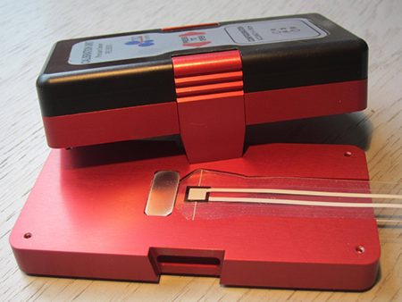
Calibration is easy and traceable. Every calibration unit is checked against a reference administered by a “National Competent Body”, ensuring that measurements are verifiable and traceable according to quality standards.
The calibration unit features very high sensitivity of +/- 0.1 N/cm2, roughly equivalent to the pressure exerted on a surface by a 2 Euro (€) coin!
Must I change the way I work?
No! If you prefer, continue using the ink stripe to set the rollers. The Pressure Indicator – Low Pressure version can serve as a control device to ensure that your pressure levels are within press-process tolerances.
Eventually, you will become accustomed to this new method. Then, to achieve maximum print stability and minimize consumable costs – start setting the rollers with the Pressure Indicator – Low Pressure version.
Stay confident that your measurements are firmly based on the principles of the offset process itself.
Specification:
- Sensor blade length: 350 mm / 13.8”
- Sensor blade thickness: 0.2 mm / 0.008”
- Optimal nip width: ≥ 5 mm / 0.2”
- Measurements per sensor: Tested up to 4 000
- Measuring units (force/area): Newton / cm2
- Measurement range
- PI - Low Pressure version: 1 – 30 Newton / cm2
- Display resolution: 1 N / cm2
- Patent: SE-519 918. Patent
- SE-1450052-4 Patent Pending
Simple to Use:
- One-button control
- Only one operator needed
- Bright LED display for easy readings
- Standard AAA batteries and power-save function
- Sensor blades can measure with either side towards either roller
- Three-step safety design to protect the operator
- Can be used on all offset presses from any manufacturer
- Delivered in a robust instrument case
Where to measure in the Printing Press:
|
Pressure Indicator instrument |
Part Number |
P102LP |
|
|
Semi-dynamic sensor blade |
Length 350 mm | Part Number |
PS35001 |
|
Calibration / Verification unit |
Part Number |
CAL25PS |
Nip Control Tool Set
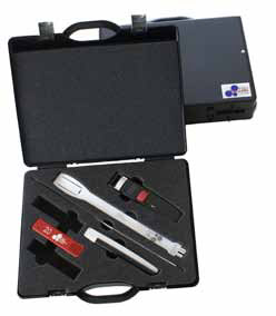
Sturdy box for both Pressure Indicator and Roller Nip Indicator instruments, calibration tool and sensor blades.
Nip Control, Roller Nip Indicator are trademarks of Nip Control AB, Sweden

