Color Specifications and Measurement Conditions
Color Specification is the number of parameters that define key factors that determine color. We know that color is a relationship between three variables: Object, Illuminant and Observer. While we mostly focus on Object properties, we should specify the other two. However, we are using Instruments, and that makes Color Specifications more complex. No two models of instruments are identical, and often there are significant differences in geometry, aperture size, and measurement conditions; and we have two additional variables: the amount of UV component in the light that is illuminating the object during measurement and potential light polarization that may help to reduce Specular Reflection issues.
In practice, Color Specification defines
- Illuminant (Standard: A, B, C, D50, D65, F1, ... F11, or custom measured)
- Observer (Standard 2° or 10°)
- M-Condition (Print Industry) or UV on/off (Color Manufacturing)
- Instrument Geometry
- Aperture
- Backing (White, Black, Self)
Why do we need Color Specifications?
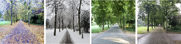
Each defined variable significantly impacts color coordinates, reflecting the intricate nature of color. This variability isn't an error but rather inherent to color's complexity. It's imperative to precisely define color measurement methodologies; otherwise, numerical data lacks utility. Unlike translating between languages, color perception is akin to observing the same landscape in different seasons—the appearance varies due to changing conditions.
Print Industry is D50/2° in most cases 0/45° or 45°/0
While Observer and illuminant are fixed, M-conditions have to be defined.
Measurement Conditions specified by ISO 13655:2017, the whole concept has been developed to control OBAs.
- M0 — simulates illumination of Standard Illuminant A (gas-filled tungsten lamp)
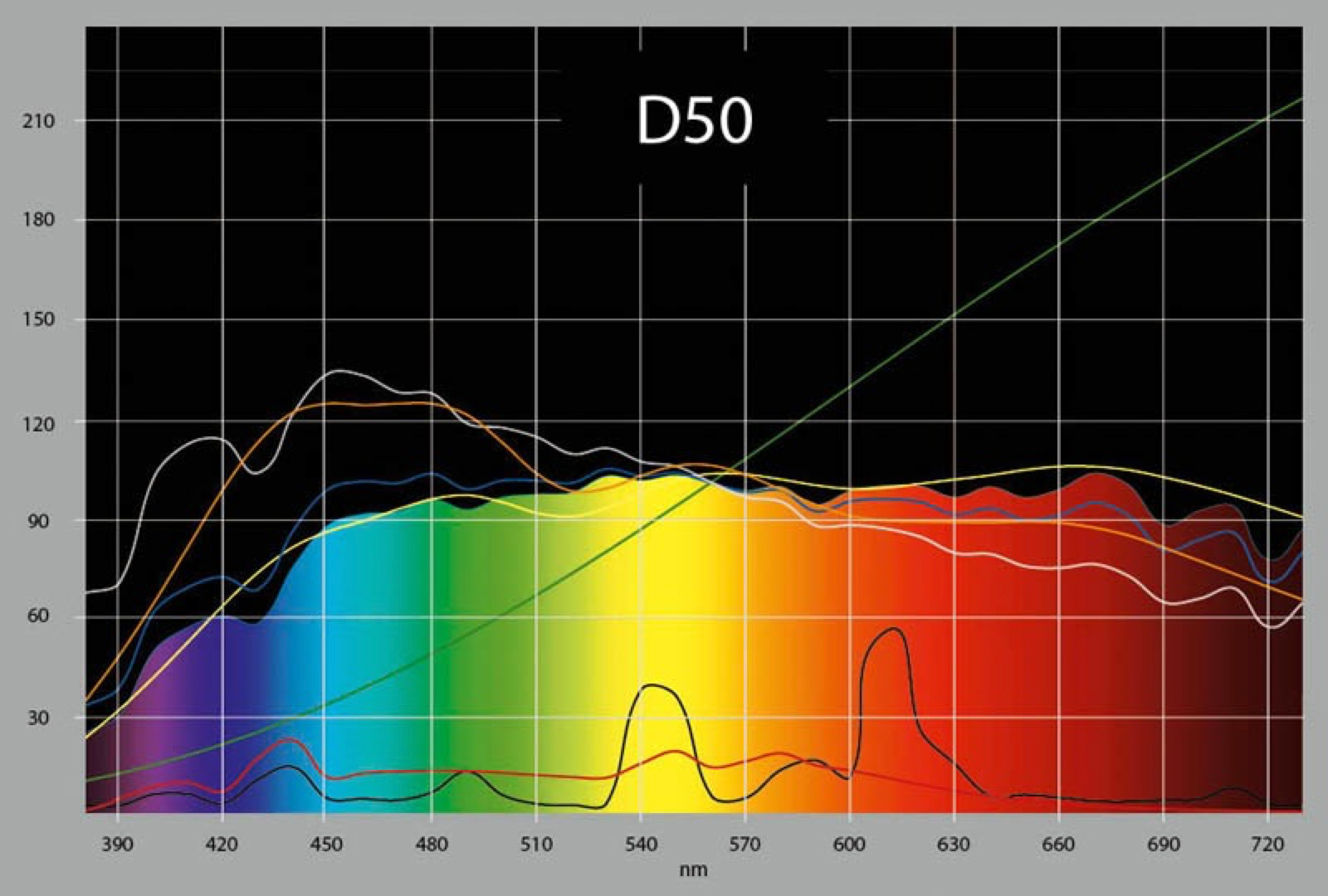
This is an older standard which, in fact, is all before new standards have been developed. When the older instrument was developed, there was no official standard to match. - M1 — simulates illumination of Standard Illuminant D50 (theoretical daylight) - today is achieved using D50 LEDs with high CRI. If the Substrate contains OBAs, it is recommended to apply M1.
- M2 — simulates illumination with a UV-cut filter. In practice, some instruments use M0/A or M1/D50 illuminant to be UV- filtered - which alters the results!
- M3 — simulates illumination with a UV-cut filter with light polarization (this is not corresponding to any human viewing conditions, measurements are typically darker than M2, and differences depend on substrate and inks. This method reduces some reflections, and that is why works in some situations better for wet inks.
Important notes about M3:
- M3 is used mostly for process control purposes and requires modified references (OK Sheet).
- None of industry-standard uses M3 for defining reference values!
- No standard defines wet ink references!
- M3 is used in Offset and LFP when printing on high glossy material.
- M3 is not dedicated to Color Management.
- M3, compared to M2, may bring some kind of information related to glossiness.
More about M-conditions
- Most of the instruments dedicated to prints today support more than one M-condition. Especially new handhelds can measure all M-conditions in a single scan; however, integrated systems usually only support one condition. Some systems measure in dual scan mode, for example, M3 for process control and M1 for evaluating against references.
- There are two standards (M1 Part 1 or M1 Part 2) of how M1 data are calculated by the instrument - some of the Instruments ( X-Rite eXact 1) give to users the ability to select their preferred one. The results are not the same.
- M1 minus M2 detects fluorescence (presence of OBAs)
- Profiles are often used as a reference data source - when using an existing one or creating a new one, it is critical not to mismatch M-condition!
- Please note that another standard: ISO 3664:2009 - which defines Lighting Conditions for visual judgments - is correlated to the same topic.
Paints, plastics, and textiles are often D65/10°, d/8°
10° Observer is, by definition, focused on larger objects — like wall paints; also, typical Illuminant is different from the used in Print Industry. Typically no-printing color manufacturing uses different geometry and, in most cases, much larger apertures.
The presence of UV is specified with less precision (on/off) - data exchange between different instruments might not be accurate. Spherical instruments offer another parameter defining specular trap open or closed (SPEX/SPIN) where results are dependent on glossiness and other properties of the specimen.
Standards and real-world scenarios
D50 and D65 are very theoretical. In practice, in both public and private spaces, we are using various sources of light. Most of them today are LED-based, replacing discharge and fluorescent lamps. Technology is evolving, and LED is leading the way to the future. Spectral differences are significant. Most department stores where goods are exposed may use lighting far from common standards. Custom lighting conditions might be a key to avoiding critical color issues with color rendering.
Color Specification in ChromaChecker
The user may use the list of common or create their own Color Specification - which is related to the defined instrument. A dedicated Color Specification tool is located in Color Inspector. 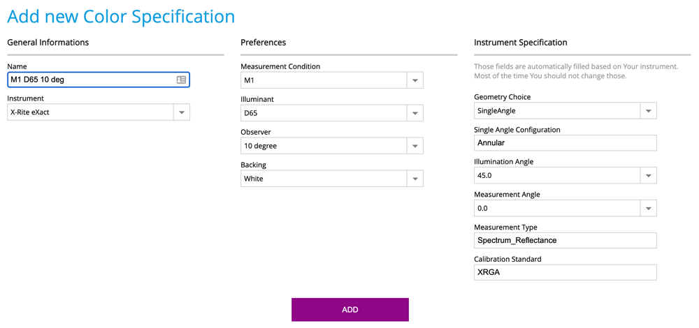
- Learn how CC Capture works with multi-M-Condition data — single measurement in QuickChecker
Contact ChromaChecker Support
Additional information and Support Form is available for logged users.