Printing using EFI Fiery RIP connected to EPSON 4900 SpectroProofer
Step 1. Defining basic configuration and goals.
Printing System Configuration:
- EFI Fiery
Fiery Command WorkStation Package : 6.7.0.318
Fiery Command WorkStation : 6.7.0.29
Calibrator 2 : 2.3.0.12
Calibrator 3 : 3.4.0.47
Color Editor : 7.3.2.15
Color Tools : 7.3.0.10
Server Manager : 7.3.2.32
Spot Pro : 1.4.0.20
Fiery Command WorkStation Package Updates : 6.7.0.196;6.7.0.196 SP1;6.7.0.318 - Epson Stylus Pro 4900 SpectroProofer
- Standard Proofing Paper, 17" x 50m, 205g/m² (C13S045007)
Instrumentation:
- SpectroProofer (ILS-30) - used for linearisation and profile creating
- X-Rite eXact + CC Capture - for PDF evaluation!
Please note that Instruments are different. The user decides to try this, taking into account that some differences might be caused by inter-instrument agreements. The QC department uses X-Rite eXacts widely, and this instrument is not supported by EFI.
Goal:
Creating tolerance documentation for clear communication with Customers. High-accuracy proofing printing of ∆E Variators and Snowflakes for contracts signing with Customers. The expected accuracy of prints should be less than 1.0 for all samples covered by the printing system gamut.
Accepted limitation.
Due to Ink supplier limitations (no M1 data for Ink Formulation) and due to historical measurements and standards, M0 has been selected.
Plans for future
- At this stage, only one proofing substrate is selected - but if the implementation is successful, another two will be added to support most of the typical print conditions.
- Future change to M1 when ink supplier upgrades ink database.
Step 2. Calibrating the selected substrate for the maximal gamut.
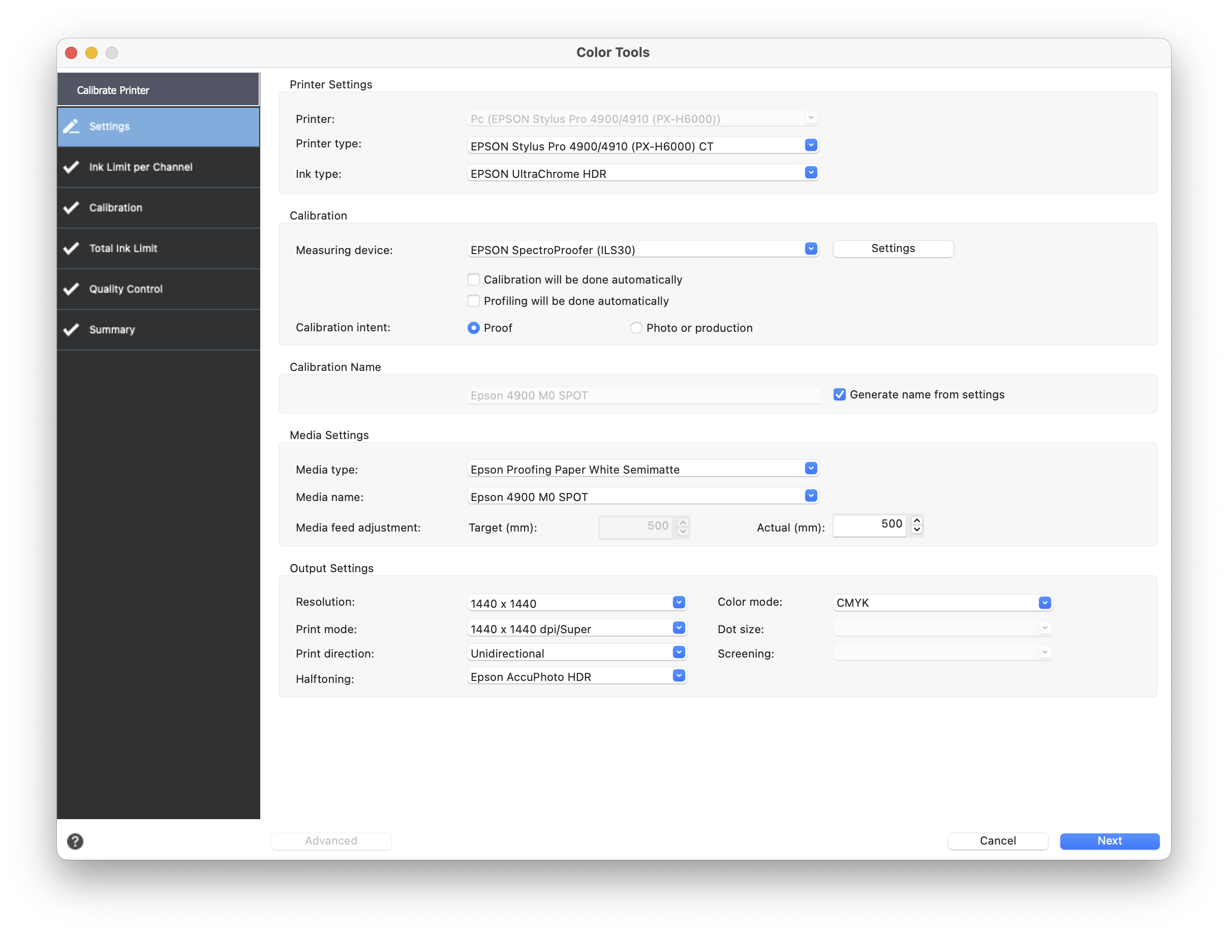
Please note that Media type selection is very important - At the first attempt, the user made a mistake that at the end gamut was narrowed. Such a mistake is hard to identify - a final ICC is generally correct, but it does not reflect what can be achieved on the current substrate/printing settings combination.
Ink Limit per Channel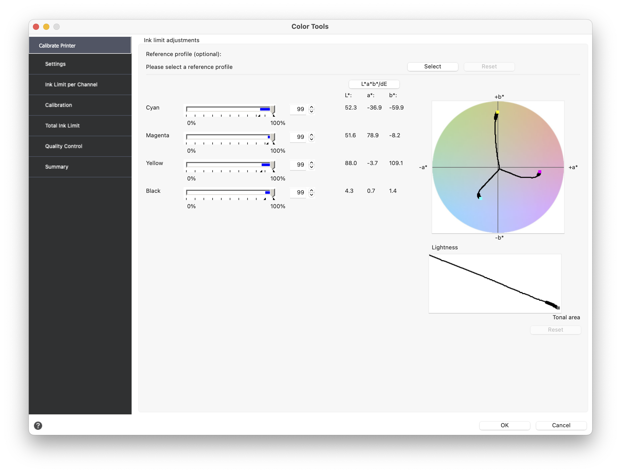
There is no reference profile, but inks should be intense and saturated. By changing the percentage and observing Lab/ LCH values, we have to make a decision on what will generate the best "corners" for our ICC profile.
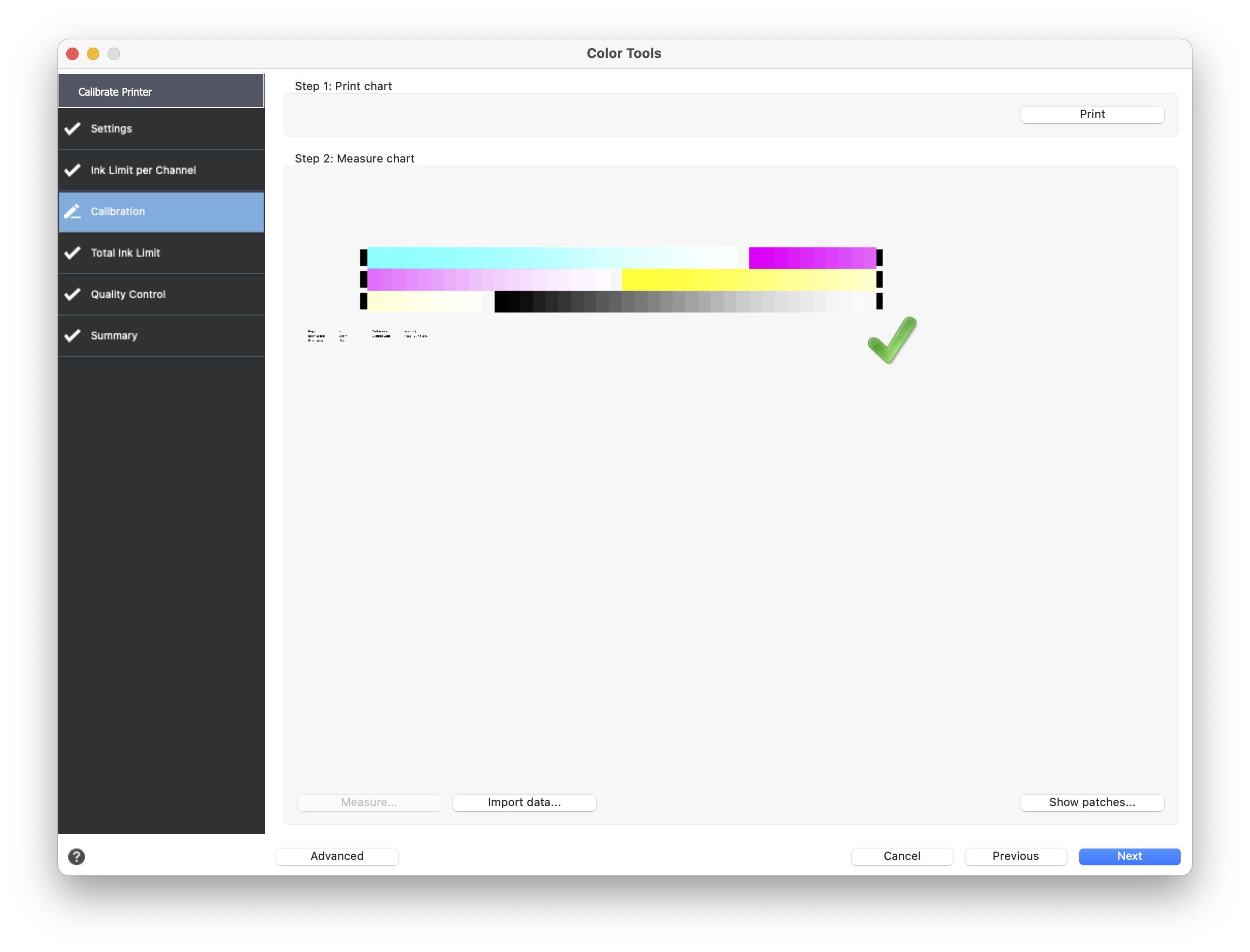
Calibration - typical steps
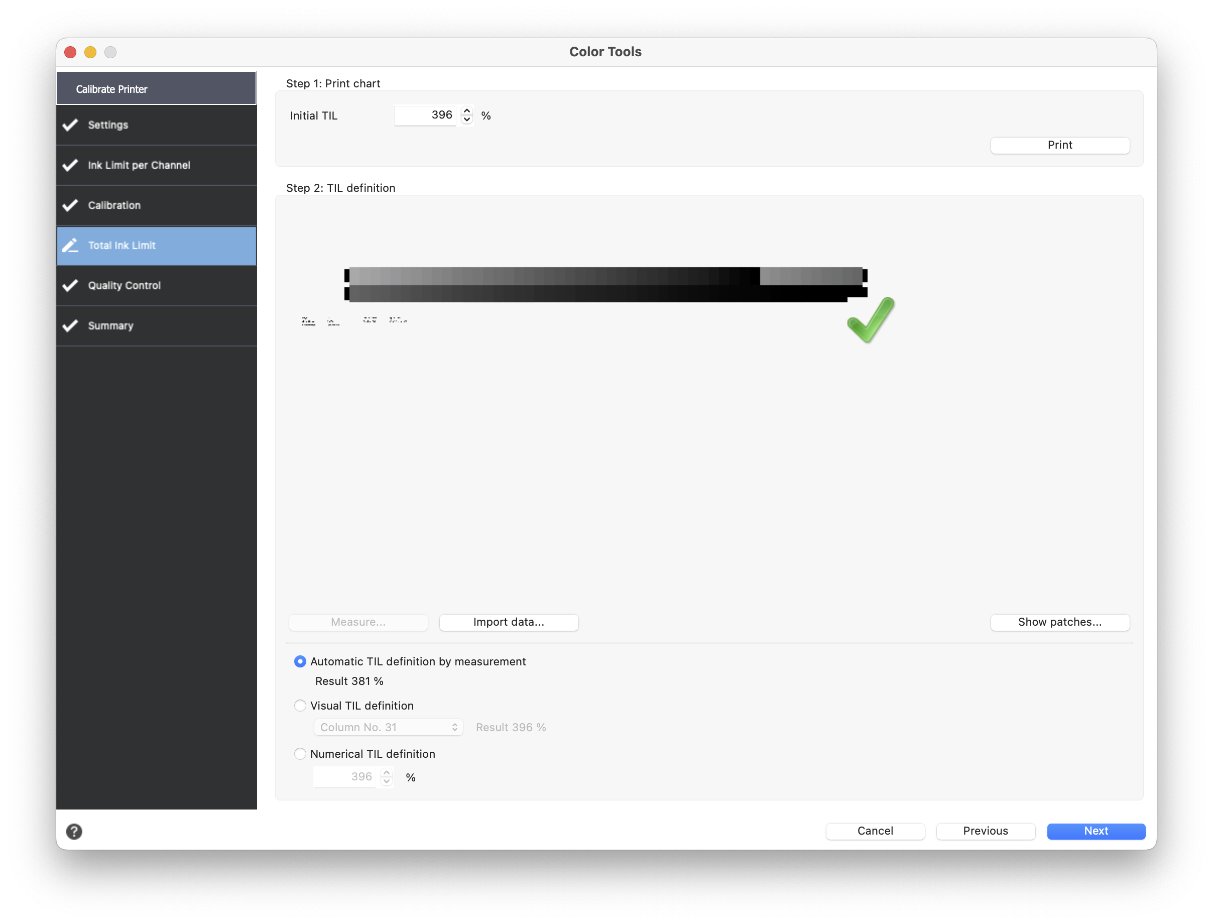
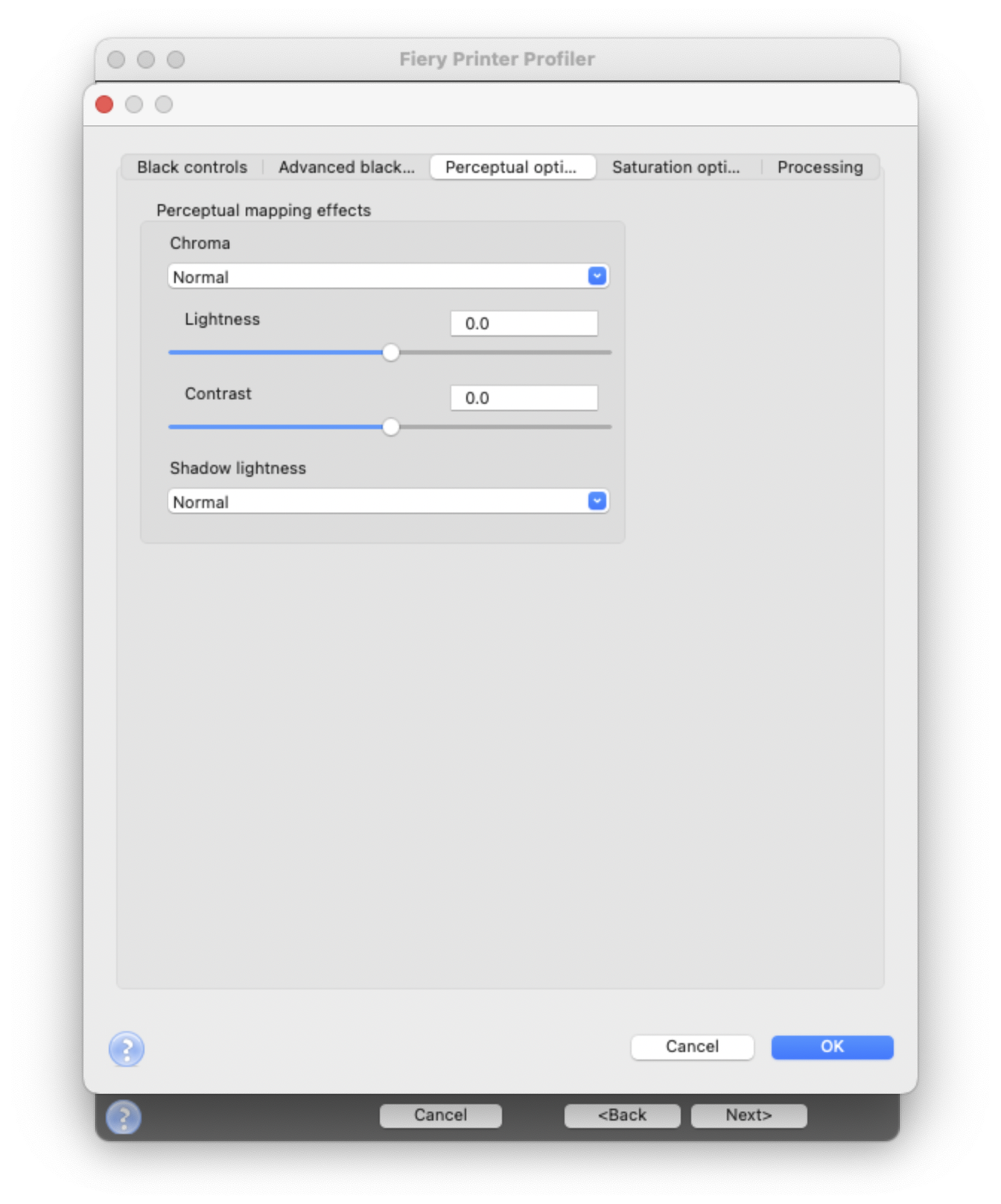
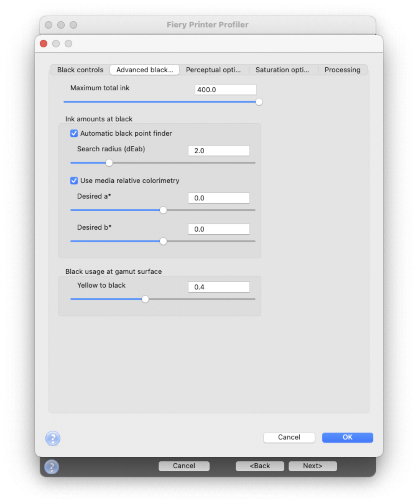
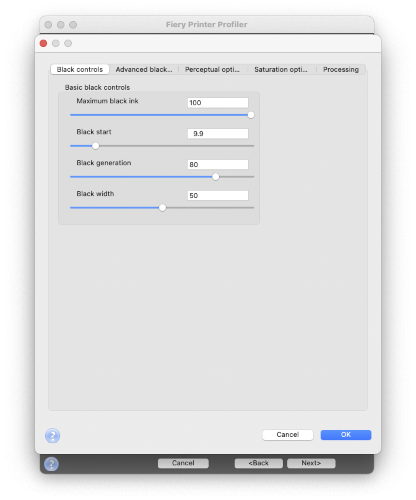
Step 3 - Profiling - setting options.
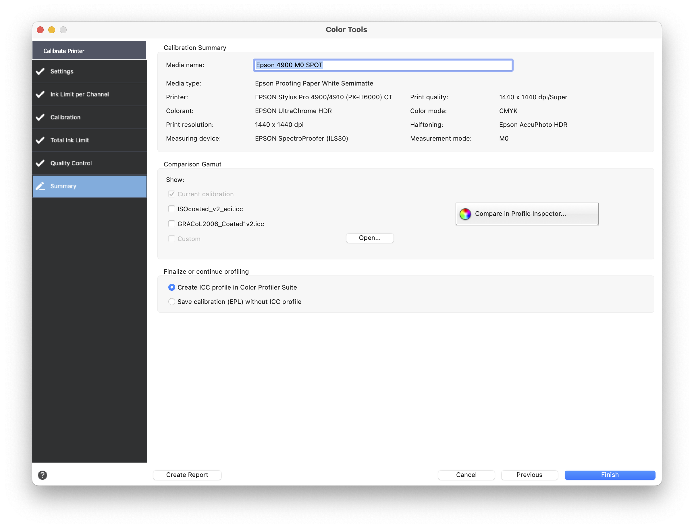
Once Calibration is complete, we can create an ICC Profile. It is important to use the biggest Patchset available - in this case, it is a layout that consists of 4028 color patches.
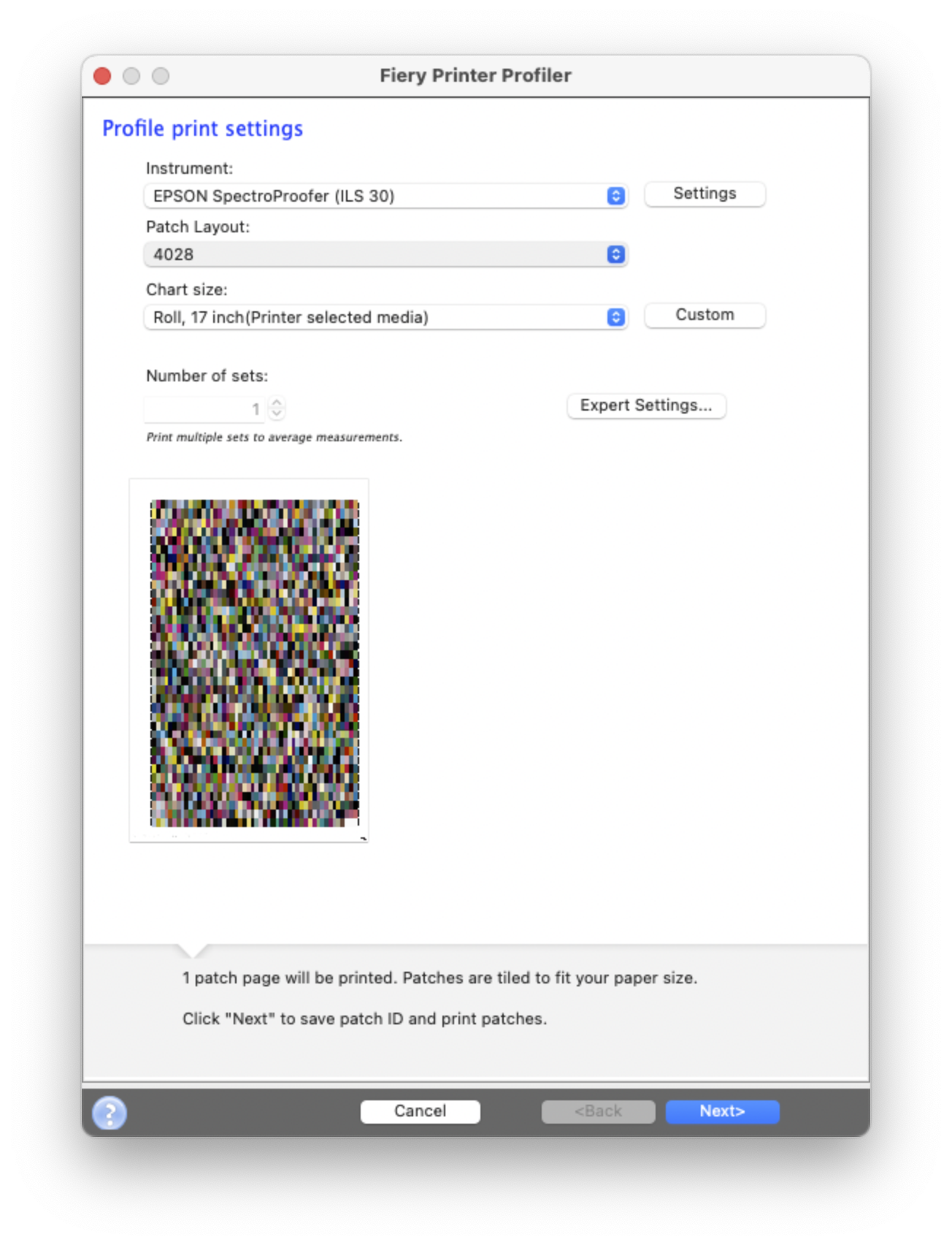
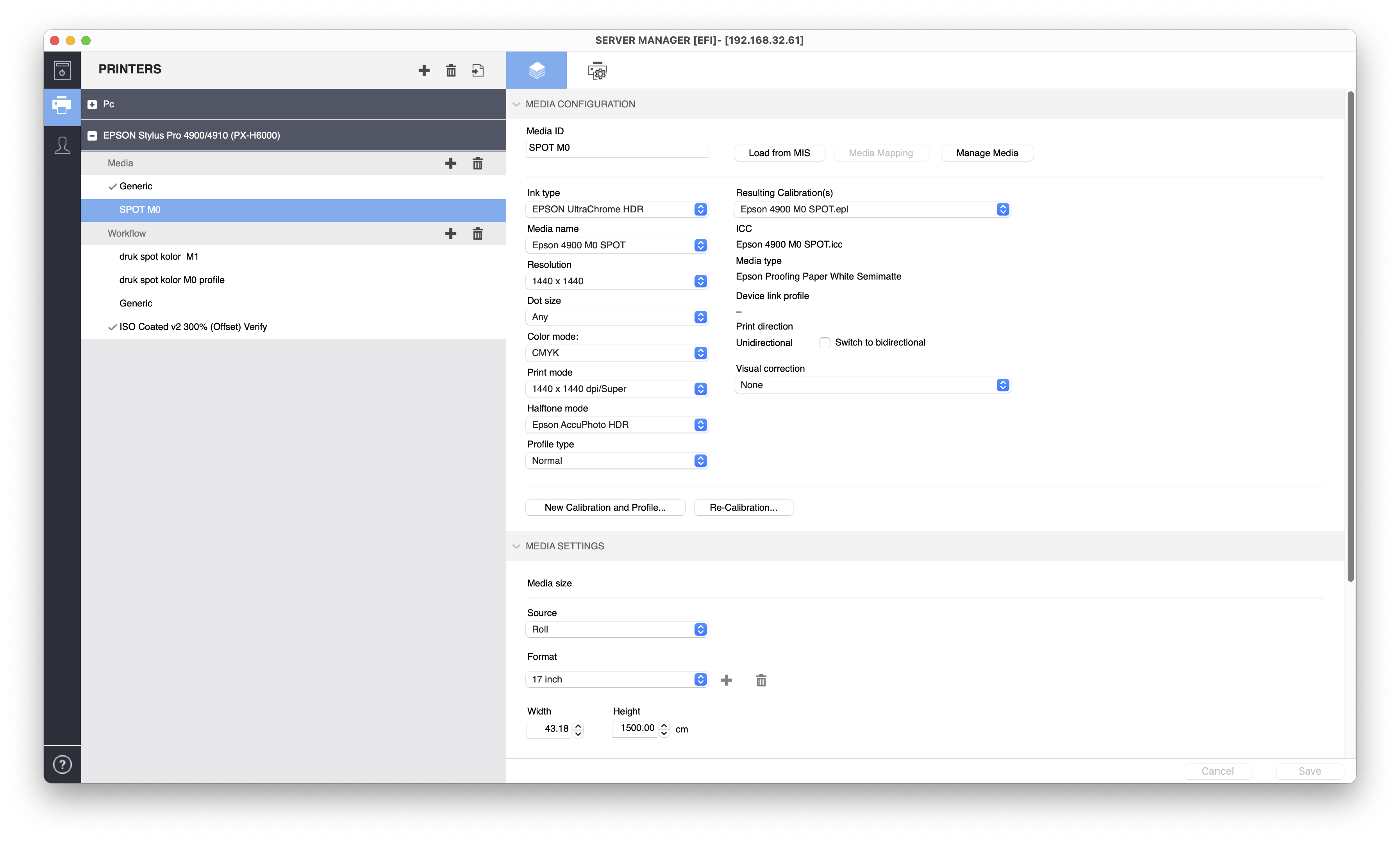
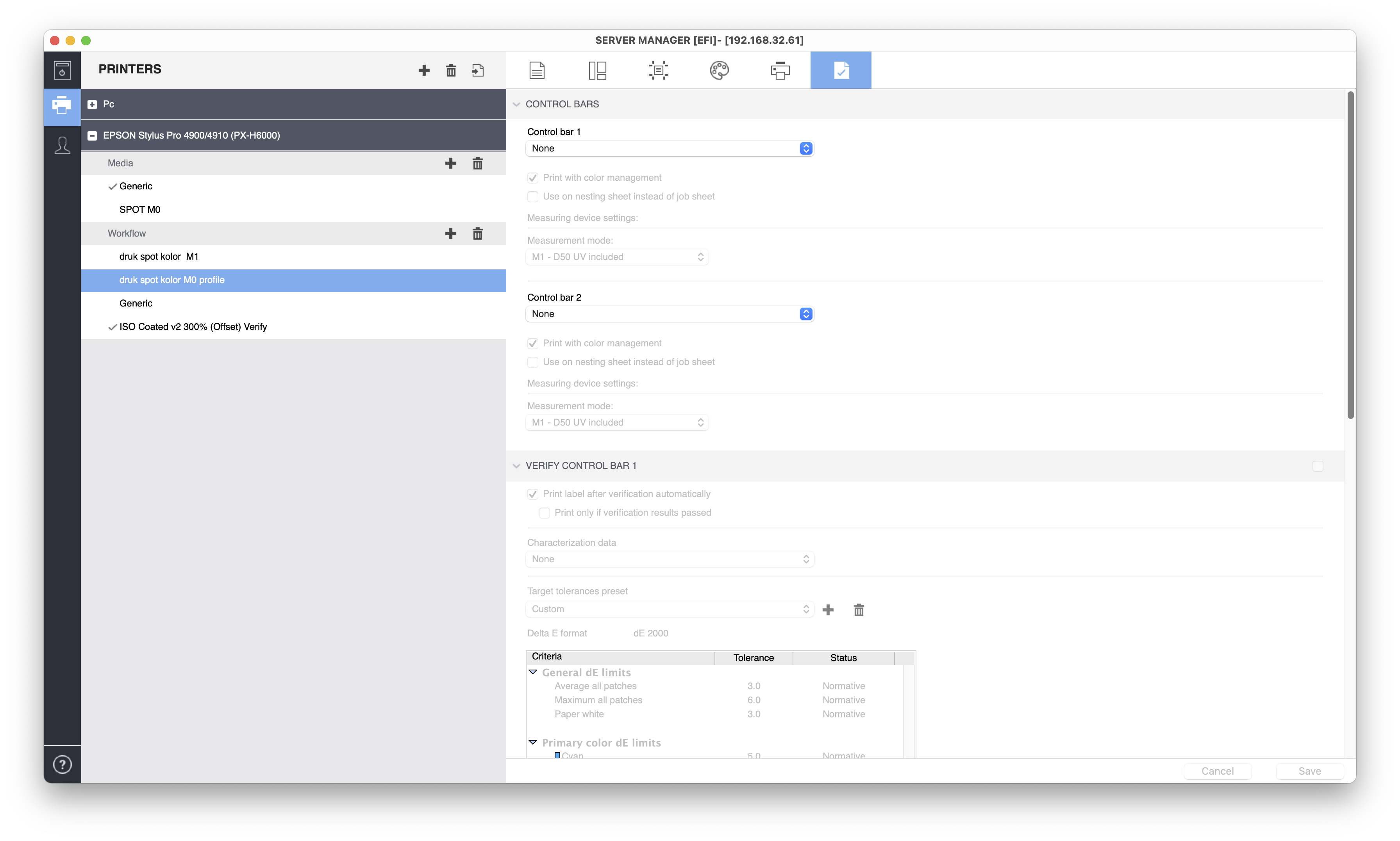
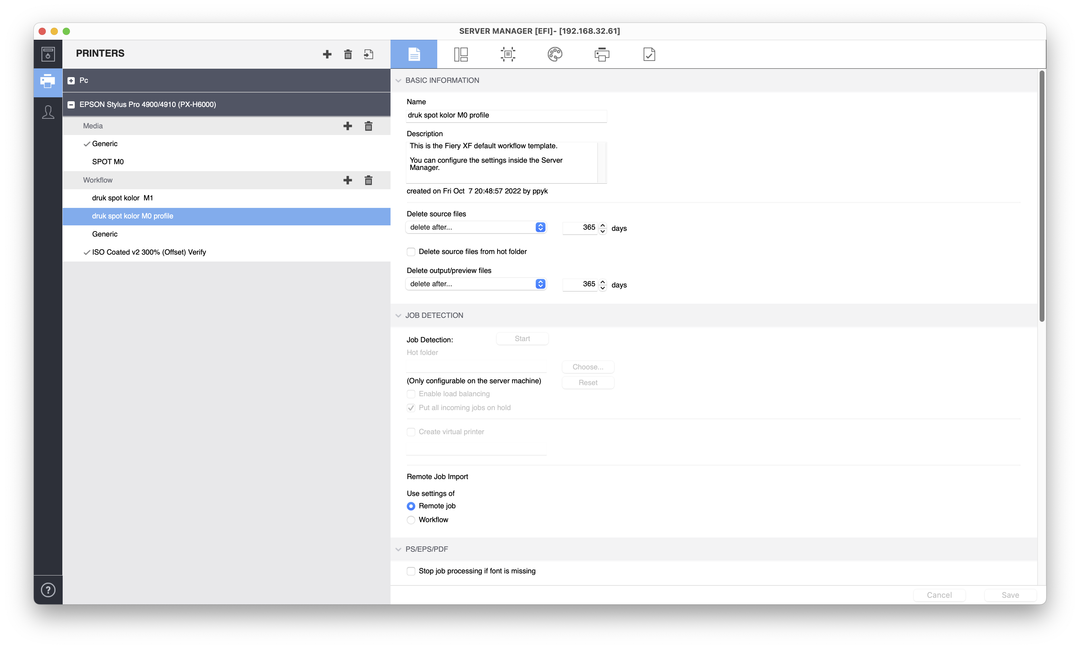
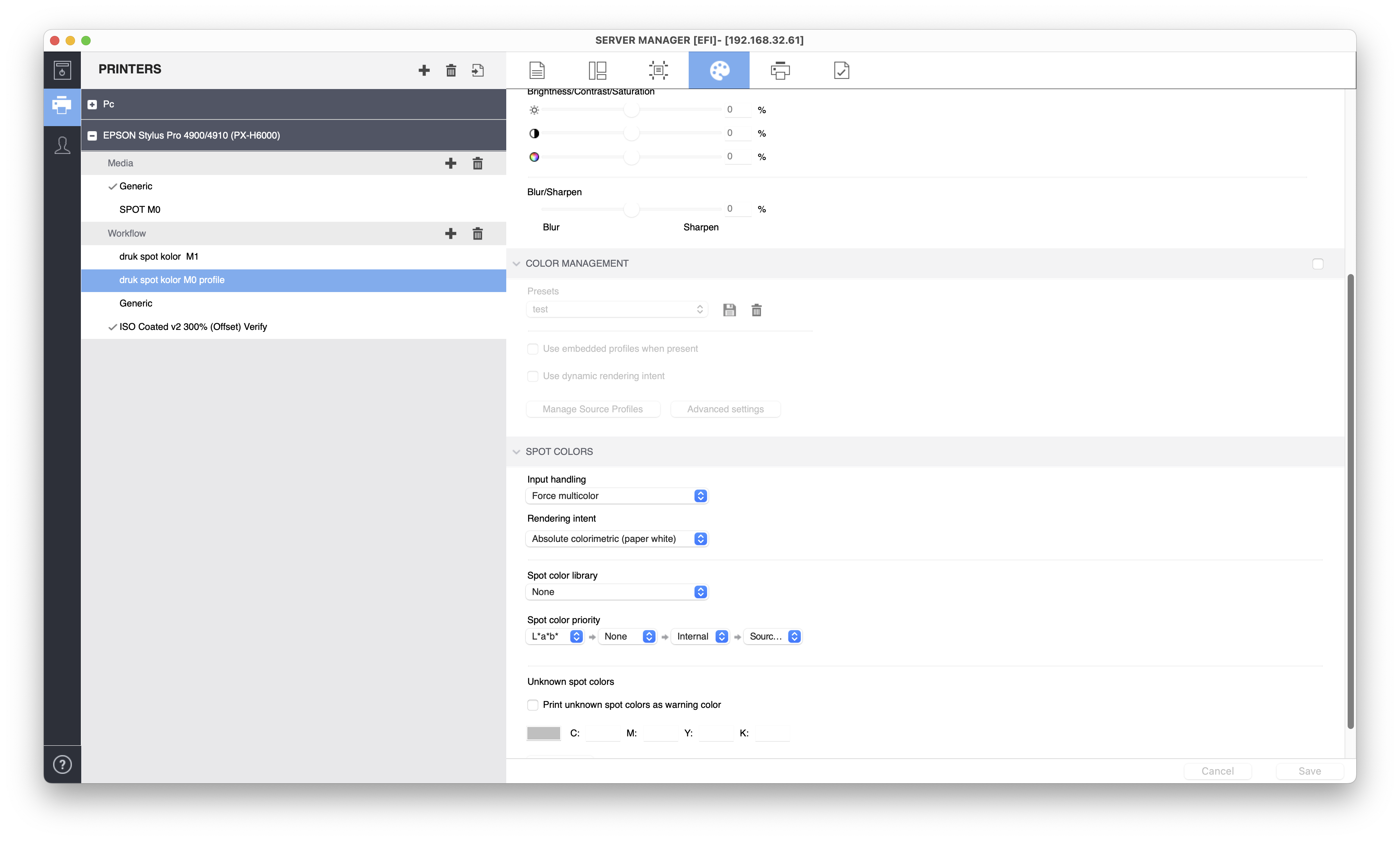
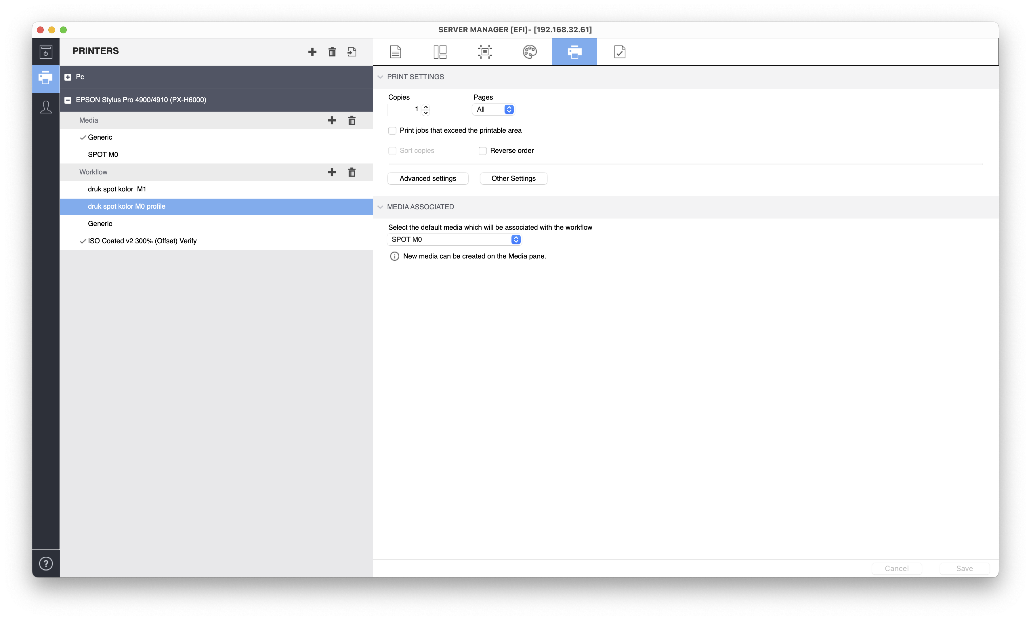
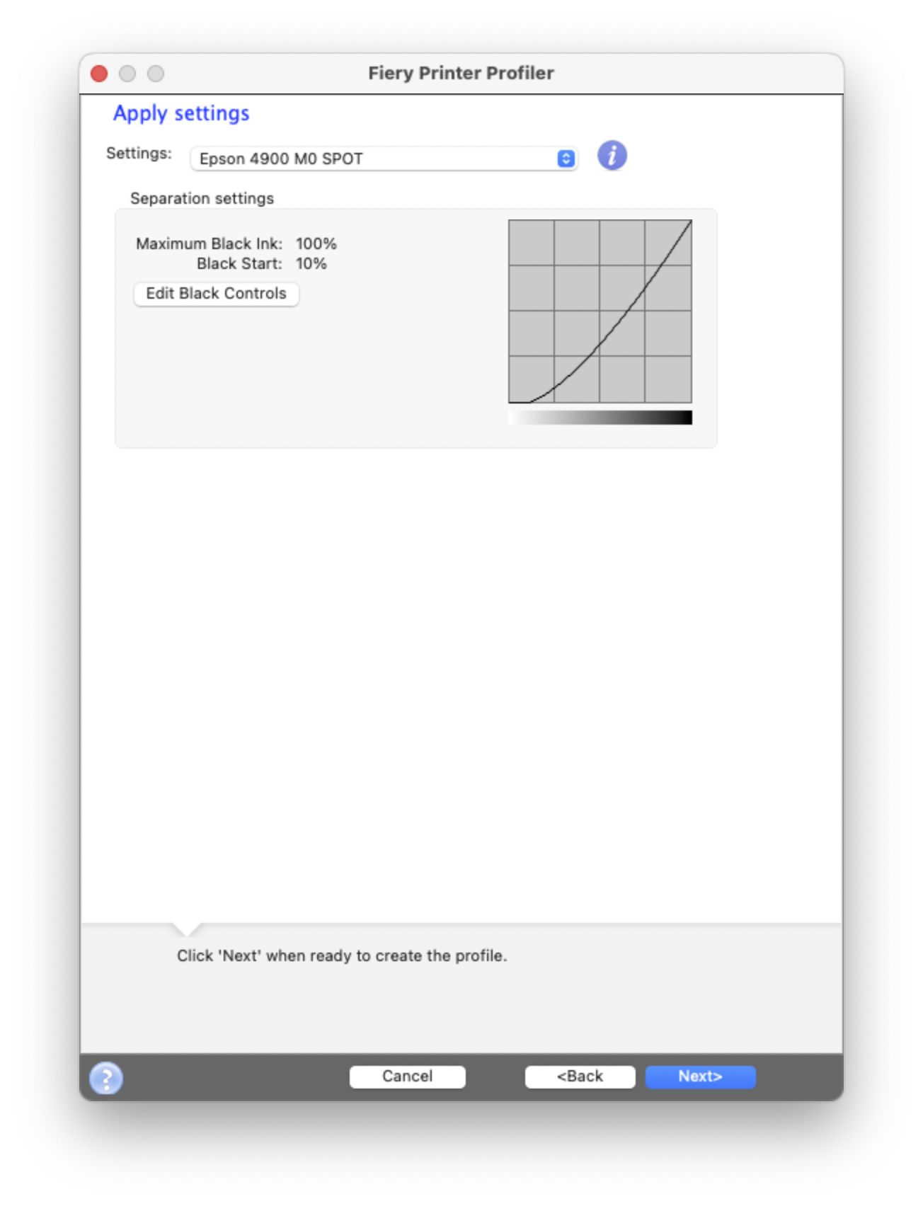
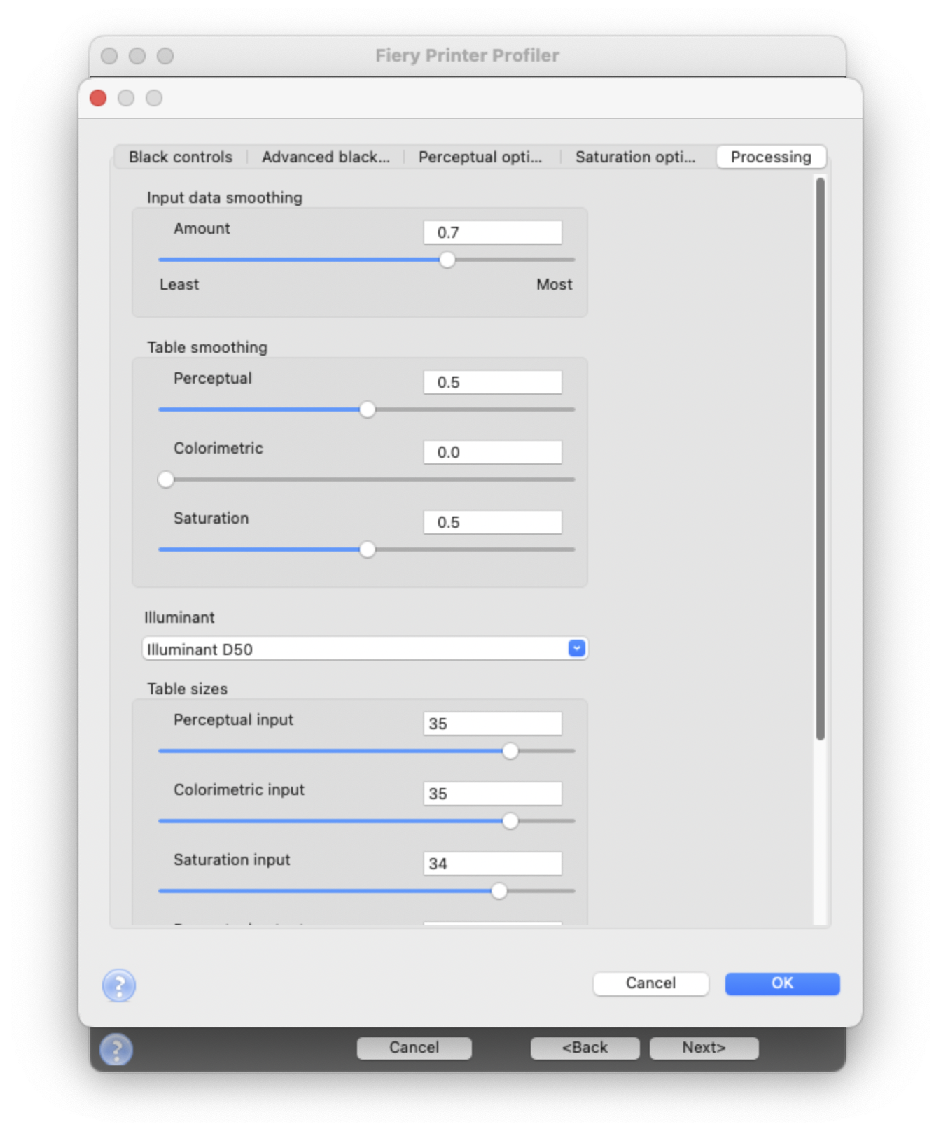
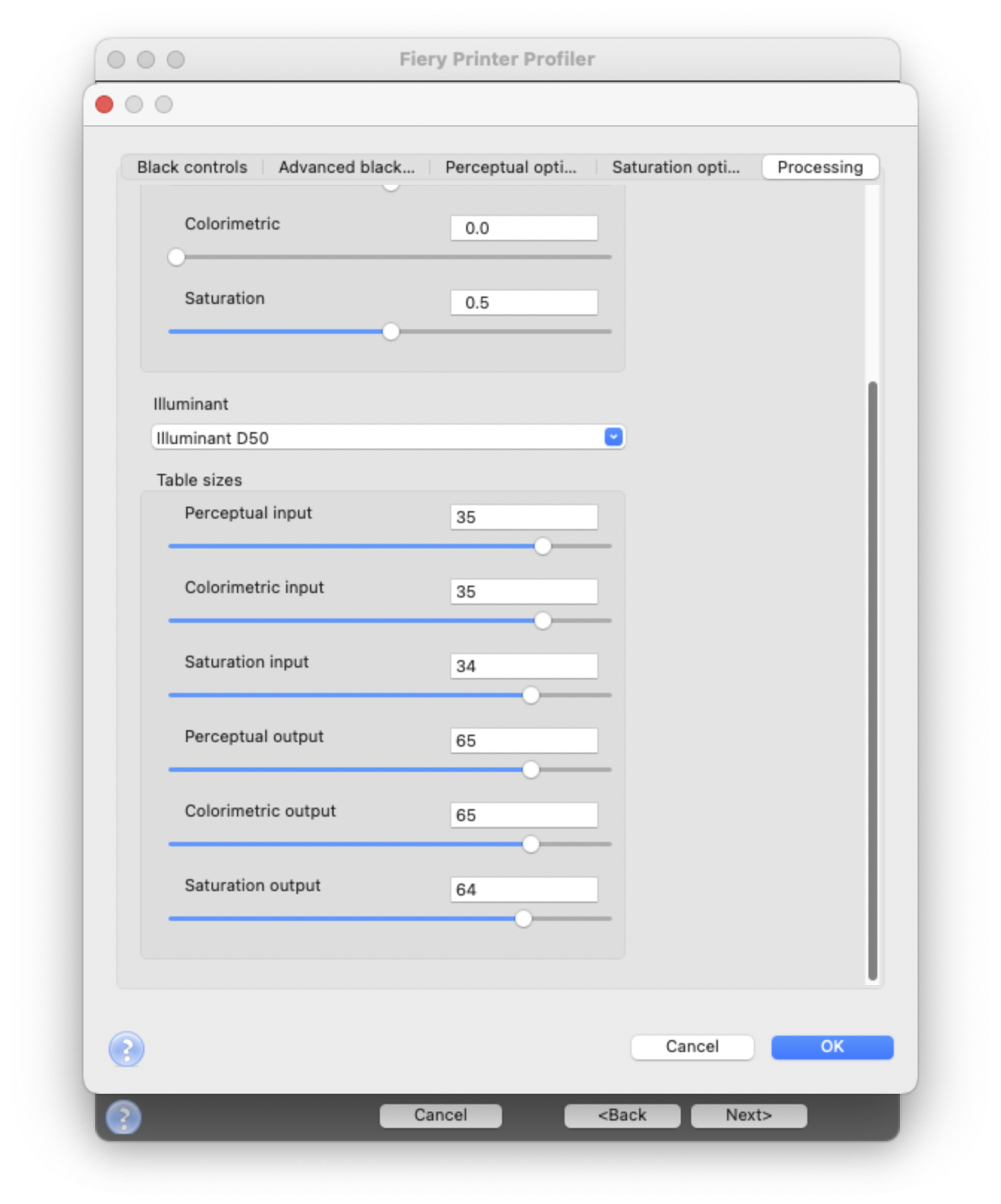
Table sizes have input on the final profile size. With maximal values, size exceeds ChromaChecker limitations.
Step 4 - Upload ICC to ChromaChecker Server.
Go to ICC Profile Inspector and upload just created one. Take care to select the proper M-condition.
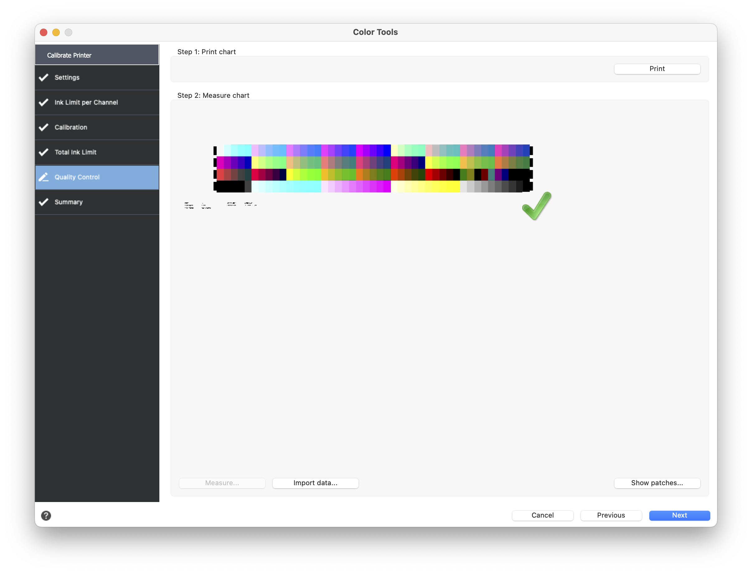
Final Step - Printing Snowflakes, Grids, or ∆E Variators.
Now in any ChromaChecker tool that creates PDF, select color space CMYK and ICC Profile created by EFI Fiery.
Results achieved with described settings.
The measured deltas are written down on a printed sheet by the ChromaChecker Champion.
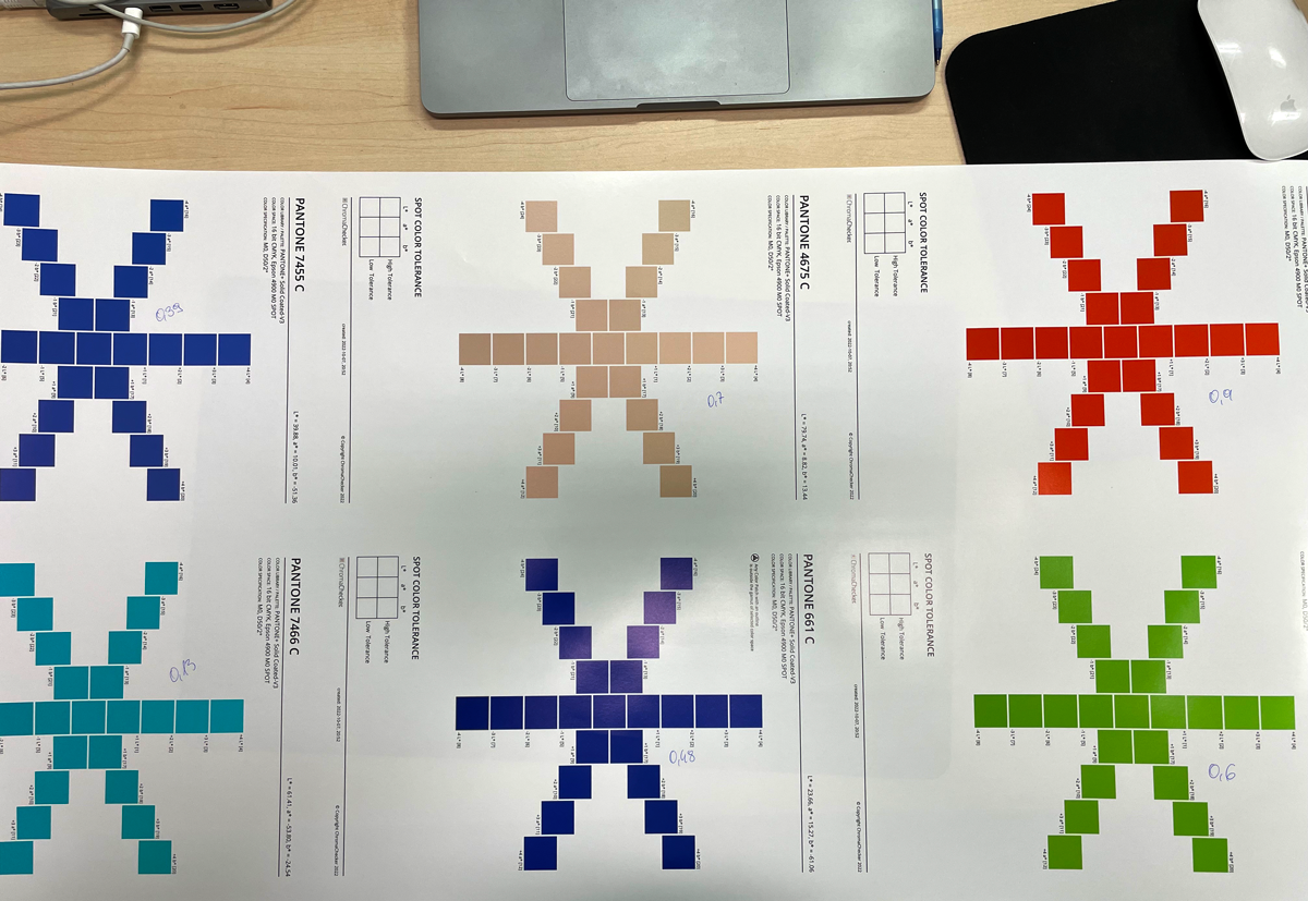
∆E 00 values are:
0.39 0.70 0.90
0.13 0.48 0.60
Congratulation!
Wireframe - Epson ICC, Flat - GRACoL

Download a sample ICC profile created by our User. You may use it for comparison purposes. This is just a sample and can't be used for production.
Acknowledgments
ChromaChecker would like to thank our User: S-Druk Company, Kraków, Poland, for providing documentation and cooperation.
Contact ChromaChecker Support
Additional information and Support Form is available for logged users.